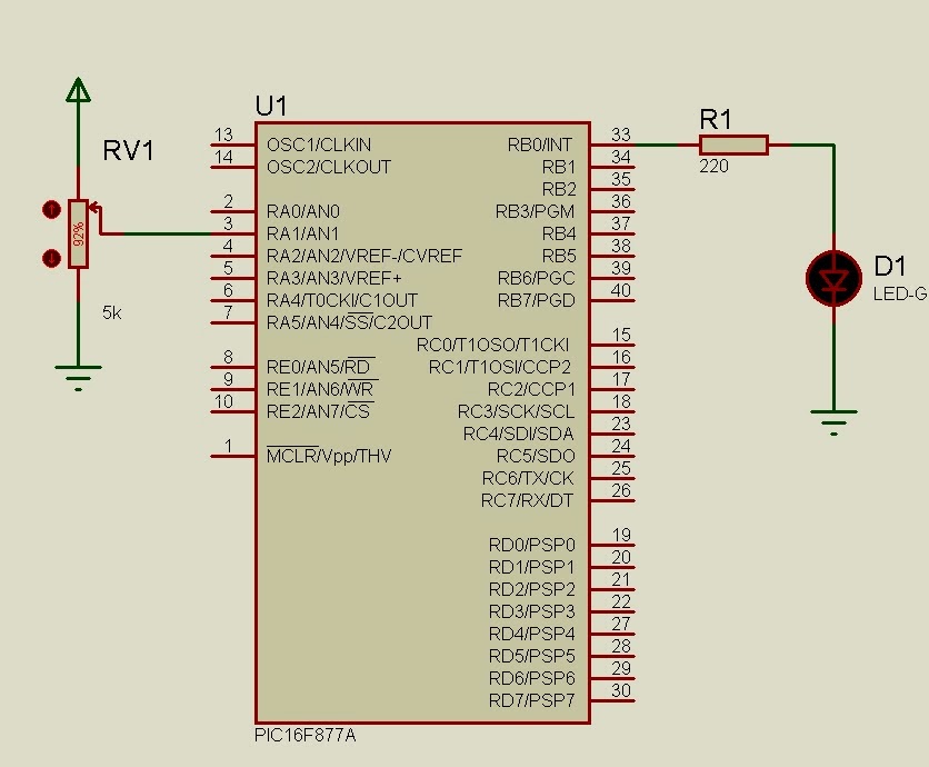
Ejemplo 1
#include <16F877a.h>
#fuses HS,NOWDT,NOPROTECT,NOLVP
#use delay(clock=4000000)
#use fast_io(B)
#use fast_io(A)
#byte portb = 6 // se definen las direcciones de memoria
#byte porta = 5
int a=0;
void main() {
set_tris_a(0xff); // se configura el puerto A como entrada
set_tris_b(0x00);
SETUP_ADC(ADC_CLOCK_INTERNAL); // el a/d funcione con un reloj interno del micro
SETUP_ADC_PORTS(AN0); // aca determianr que el puerto RA0 será analógico
SET_ADC_CHANNEL(0); // el canal con el que trabajas, en este caso 0 por el RA0
while(true){
a=READ_ADC(); // lee el canal analogico seleccionado
output_high(pin_B0) ;
delay_ms(a);
output_low(pin_B0);
delay_ms(a);
}
}
Ejemplo 2
#include <16F877A.h>
#device adc=10 //resolucion de 1024 valores
#FUSES NOWDT //No Watch Dog Timer
#FUSES HS //High speed Osc (> 4mhz for PCM/PCH) (>10mhz for PCD)
#FUSES NOPUT //No Power Up Timer
#FUSES NOPROTECT //Code not protected from reading
#FUSES NODEBUG //No Debug mode for ICD
#FUSES NOBROWNOUT //No brownout reset
#FUSES NOLVP //No low voltage prgming, B3(PIC16) or B5(PIC18) used for I/O
#FUSES NOCPD //No EE protection
#FUSES NOWRT //Program memory not write protected
#use delay(clock=4000000) //oscilador externo de 4MHz
#include <LCD.C>
float a=0;
void main()
{
setup_adc_ports(AN0_AN1_AN3); setup_adc(ADC_CLOCK_DIV_2);
setup_spi(SPI_SS_DISABLED);
setup_timer_0(RTCC_INTERNAL|RTCC_DIV_1);
setup_timer_1(T1_DISABLED);
setup_timer_2(T2_DISABLED,0,1);
setup_comparator(NC_NC_NC_NC);
setup_vref(FALSE);
lcd_init();
while(true){
set_adc_channel(0);
a=read_adc();
printf(lcd_putc,"\f");
printf(lcd_putc,"Valor Digital");
lcd_gotoxy(1,2);
printf(lcd_putc,"%f",a);
delay_ms(100);
}
}
Ejemplo 3
#include <16F877A.h>
#use delay(clock=4000000)
#fuses NOWDT,NOPUT,NOPROTECT,NOBROWNOUT,NOLVP,NOPROTECT,HS,NOWRT,NODEBUG
#use fast_io(A)
#use fast_io(B)
#use fast_io(C) /// con esta instruccion evitamos que
#byte porta = 5
#byte portb = 6
#byte portc = 7 /// se definen direcciones de memoria
int canal0=0;
int unidades=0;
int decenas=0;
int centenas=0;
void main ()
{
BYTE data[10]={0x3F,0x06,0x5B,0x4F,0x66,0x6D,0x7D,0x07,0x7F,0x6F};
set_tris_b(0b00000000);
set_tris_c(0b00000000);
output_low(pin_c0);
output_low(pin_c1);
output_low(pin_c2);
SETUP_ADC(ADC_CLOCK_INTERNAL); // declaramos que el reloj del adc sera interno
setup_adc_ports(all_analog); // todos los canales analogicos habilitados
SET_ADC_CHANNEL(0); // seleccionamos canal 0
DISABLE_INTERRUPTS(global);
while(true)
{
canal0= READ_ADC(); // retardo para esperar que el adc termine
// conversion fabricante menciona que al
// menos 50 microsegundos
delay_ms(1);
centenas=canal0/100;
decenas=(canal0 - (centenas*100))/10;
unidades=(canal0 - (centenas*100) - (decenas*10));
output_b(data[unidades]);
output_high(pin_c1);
output_high(pin_c2);
output_low(pin_c0);
delay_ms(1);
output_b(data[decenas]);
output_high(pin_c0);
output_high(pin_c2);
output_low(pin_c1);
delay_ms(1);
output_b(data[centenas]);
output_high(pin_c1);
output_high(pin_c0);
output_low(pin_c2);
delay_ms(1);
}
}

No hay comentarios:
Publicar un comentario